The lsn d series central lighting inverter provides a centralized solution to emergency lighting and power back up with a wide array of options designed to minimize maintenance requirements and optimize emergency lighting performance.
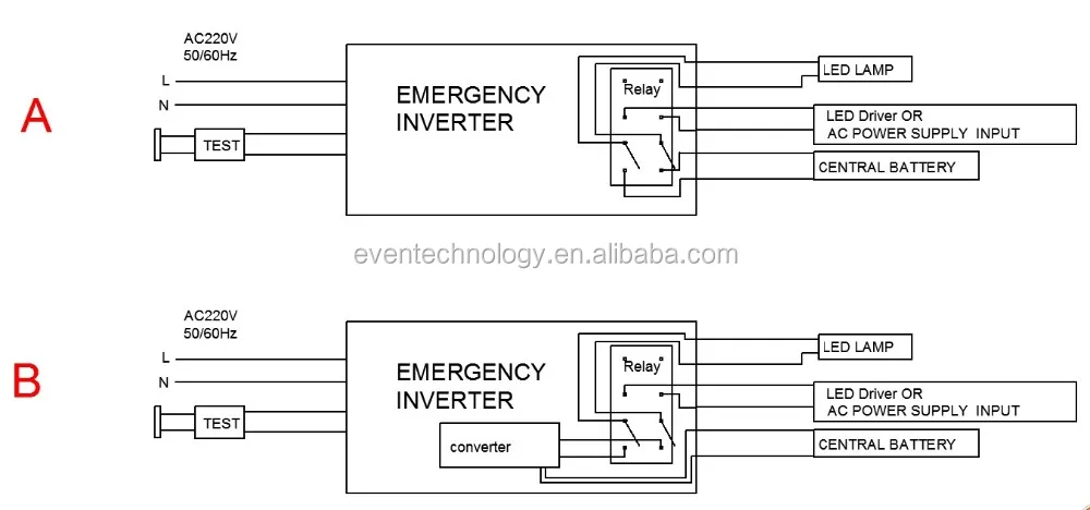
Central lighting inverter wiring diagram.
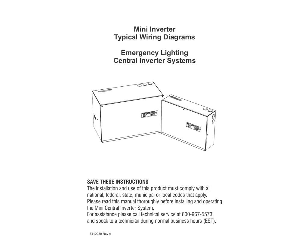
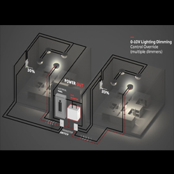
Wiring diagram 4 circuit outputs with multiple wiring your emergency lighting using a mini inverter in switched normally on lights multiple swi wiring diagram one 0 10v dimming control wiring your emergency lighting using a mini inverter in 0 10v lighting dimming control override wiring diagram multiple 0 10v dimming control.
Product description inv 400 va w 120 v out less batt.
Catalog number upc product description.
Diagrams show single zone.
Central inverter basics 2.
How to wire solar panel to 220 v inverter 12v battery 12v dc load and 220v ac load 220v fan light etc ac dc load.
Performed within 6 months of inverter shipment to maintain 2 yr.
Product description inv 400 va w 277 v out less batt.
Dls series single phase central lighting inverter.
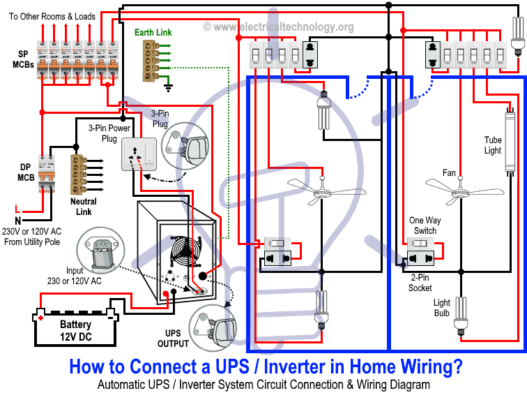
Manual ups wiring diagram with change over switch system.
Emergency lighting wiring diagrams when using a central inverter this document provides fully compliant 2017 nfpa 70 nec article 700 wiring diagrams using a central emergency lighting inverter and ul924 approved emergency lighting control device elcd.
Order a quantity of 1 per system.
Wiring schematics and load calculations explained 4.
Common terms for inverter schematics 6.
Central inverter basics lighting inverters ensure uninterrupted power to devices in times of power outages.
Evenlite s liteminder central inverter system provides an innovative emergency lighting solution for today s complex energy saving systems light sources and maintenance requirements.
Systems powered up by others are done so at their own risk.
2 summary generalpresentation page1 2 singlephasecompactsystems page3 4 singlephaseinterruptiblesystems page5 6 singlephasefasttransfersystems page7 8.
Typical wiring diagram emergency lighting mini central inverter system black white blue white brown black switched command signal violet earth ground green input wiring line switched output neutral normally on normally off output wiring neutral light fixtures led hid incandescent or fluorescent cap off unused wires diagram 1.
Automatic ups system wiring diagram in case of some items depends on ups and rest depends on main power at office or home.


